
第06章 实现Modbus通信
6.1 电机项目:移植FreeModbus
6.1.1 FreeModbus 概述
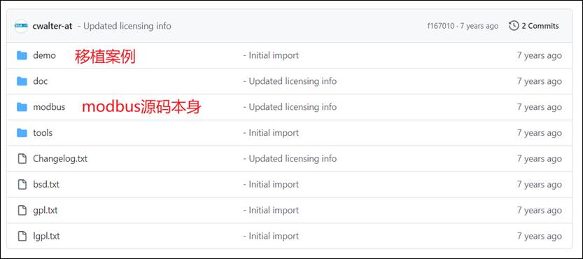
FreeModbus 是一款开源的 Modbus 协议栈,最初由 奥地利工程师 Christian Walter 开发,专为资源受限的嵌入式设备(如 STM32)优化,代码结构清晰,便于移植。
- 采用开源协议(如 BSD 许可证),允许开发者自由使用、修改和集成到项目中。
- 从站(Slave)模式完全开源,主站(Master)模式需付费或依赖社区扩展
- 支持 Modbus RTU(基于 RS-485/RS-232)和 Modbus TCP(基于以太网)
源码地址:
https://github.com/cwalter-at/freemodbus
源码目录
源码移植
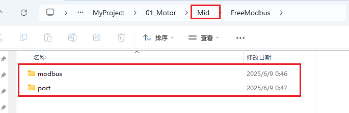
在项目文件夹 Mid 模块中新建 FreeModbus 目录,将 modbus 目录拷贝到该目录下(其中包含TCP协议内容,可加可不加);
找到 demo 中 BARE 文件夹,将其中的 port 拷贝到 Freemodbus 目录下面。
最终目录结构如下图所示:
修改 Keil 配置添加文件路径
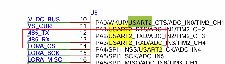
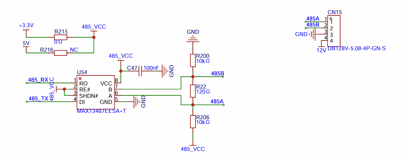
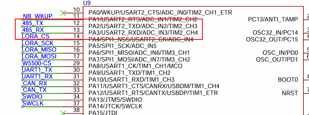
6.1.2 串口设置
① 原理图
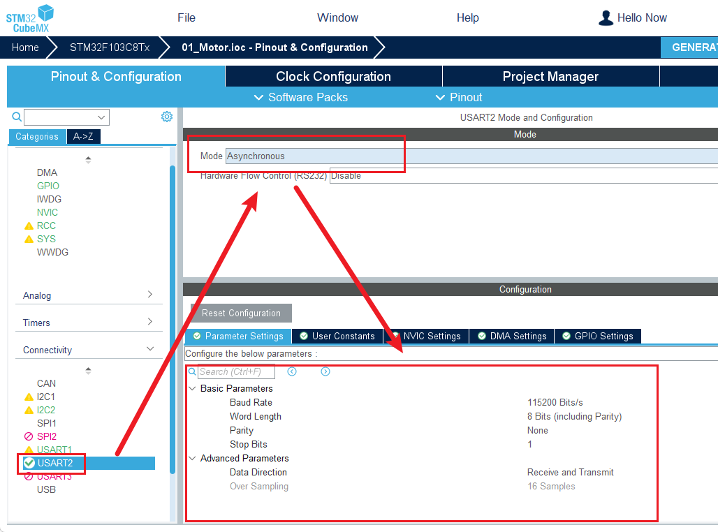
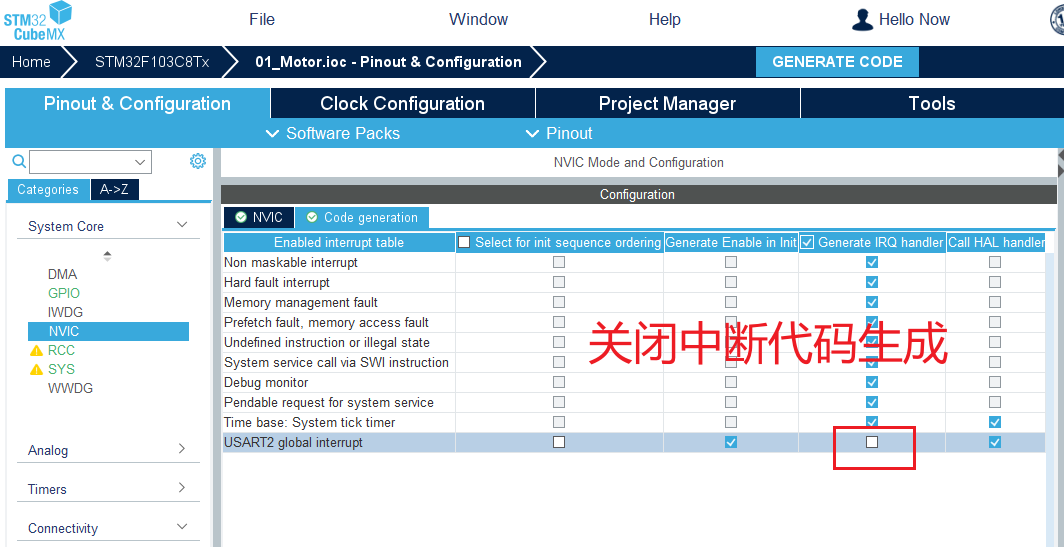
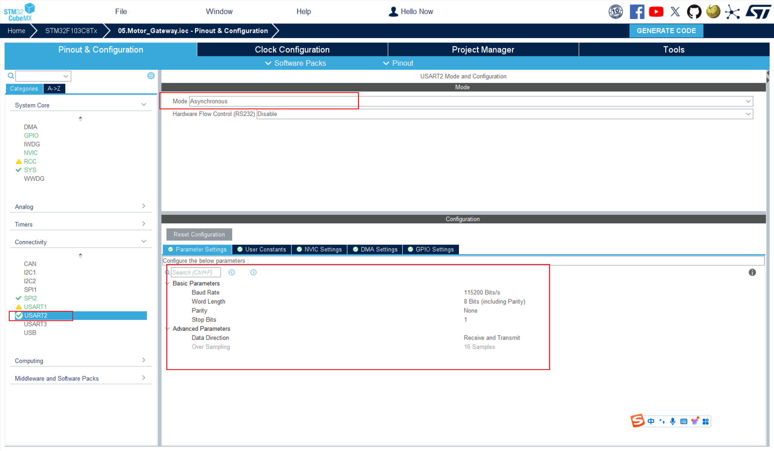
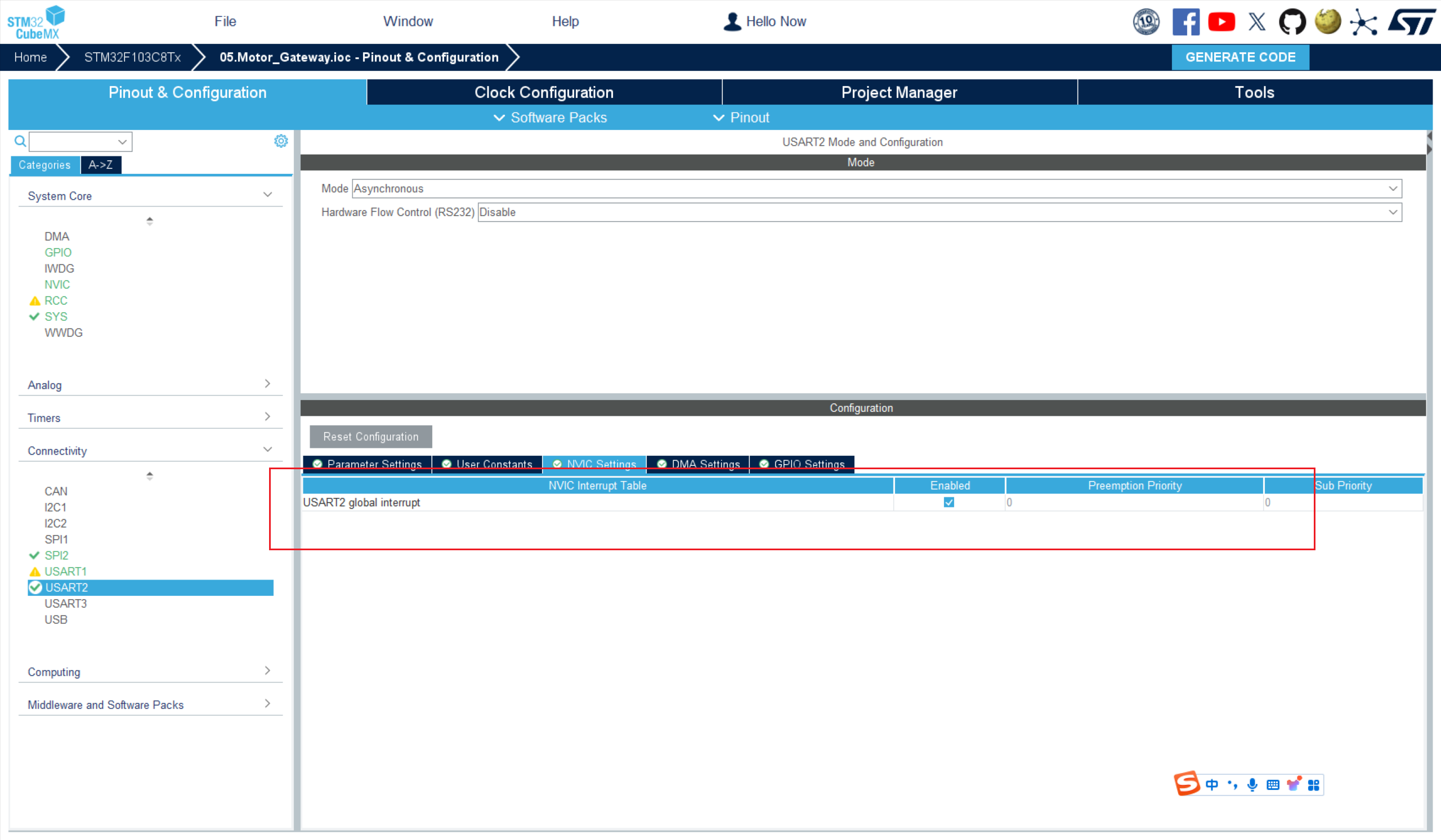
② CubeMx 配置
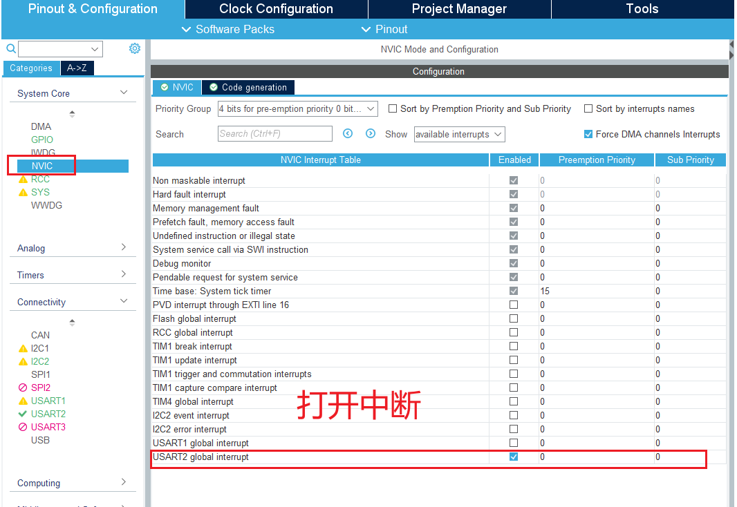
③ 代码实现
FreeModbus/modbus/port.h
添加 #include "usart.h"
FreeModbus/modbus/portserial.c
#include "port.h"
/* ----------------------- Modbus includes ----------------------------------*/
#include "mb.h"
#include "mbport.h"
/* ----------------------- static functions ---------------------------------*/
static void prvvUARTTxReadyISR(void);
static void prvvUARTRxISR(void);
/* ----------------------- Start implementation -----------------------------*/
// 开启和关闭串口中断
void vMBPortSerialEnable(BOOL xRxEnable, BOOL xTxEnable)
{
/* If xRXEnable enable serial receive interrupts. If xTxENable enable
* transmitter empty interrupts.
*/
// 1. 开启和关闭接收中断
if (xRxEnable)
{
// 开启接收中断
__HAL_UART_ENABLE_IT(&huart2, UART_IT_RXNE);
}
else
{
// 关闭接收中断
__HAL_UART_DISABLE_IT(&huart2, UART_IT_RXNE);
}
// 2. 开启和关闭发送中断
if (xTxEnable)
{
// 开启发送中断
__HAL_UART_ENABLE_IT(&huart2, UART_IT_TXE);
}
else
{
// 关闭发送中断
__HAL_UART_DISABLE_IT(&huart2, UART_IT_TXE);
}
}
// 初始化串口,HAL生成的代码已经初始化了串口,
BOOL xMBPortSerialInit(UCHAR ucPORT, ULONG ulBaudRate, UCHAR ucDataBits, eMBParity eParity)
{
// MX_USART2_UART_Init();
// return FALSE;
return TRUE;
}
BOOL xMBPortSerialPutByte(CHAR ucByte)
{
/* Put a byte in the UARTs transmit buffer. This function is called
* by the protocol stack if pxMBFrameCBTransmitterEmpty( ) has been
* called. */
USART2->DR = ucByte;
return TRUE;
}
BOOL xMBPortSerialGetByte(CHAR *pucByte)
{
/* Return the byte in the UARTs receive buffer. This function is called
* by the protocol stack after pxMBFrameCBByteReceived( ) has been called.
*/
*pucByte = (CHAR)USART2->DR;
return TRUE;
}
/* Create an interrupt handler for the transmit buffer empty interrupt
* (or an equivalent) for your target processor. This function should then
* call pxMBFrameCBTransmitterEmpty( ) which tells the protocol stack that
* a new character can be sent. The protocol stack will then call
* xMBPortSerialPutByte( ) to send the character.
*/
// 该静态函数无需修改代码,会在中断服务函数中调用
static void prvvUARTTxReadyISR(void)
{
pxMBFrameCBTransmitterEmpty();
}
/* Create an interrupt handler for the receive interrupt for your target
* processor. This function should then call pxMBFrameCBByteReceived( ). The
* protocol stack will then call xMBPortSerialGetByte( ) to retrieve the
* character.
*/
// 该静态函数无需修改代码,会在中断服务函数中调用
static void prvvUARTRxISR(void)
{
pxMBFrameCBByteReceived();
}
// 定义USART2的中断服务函数
void USART2_IRQHandler(void)
{
// 1.检查是否是发送中断
if (__HAL_UART_GET_FLAG(&huart2, UART_FLAG_TXE))
{
// 清除中断标志位
__HAL_UART_CLEAR_FLAG(&huart2, UART_FLAG_TXE);
// 调用发送中断服务函数
prvvUARTTxReadyISR();
}
// 2. 检查是否是接收中断
if (__HAL_UART_GET_FLAG(&huart2, UART_FLAG_RXNE))
{
// 清除中断标志位
__HAL_UART_CLEAR_FLAG(&huart2, UART_FLAG_RXNE);
// 调用接收中断服务函数
prvvUARTRxISR();
}
// 调用HAL库提供处理串口中断的逻辑的函数
HAL_UART_IRQHandler(&huart2);
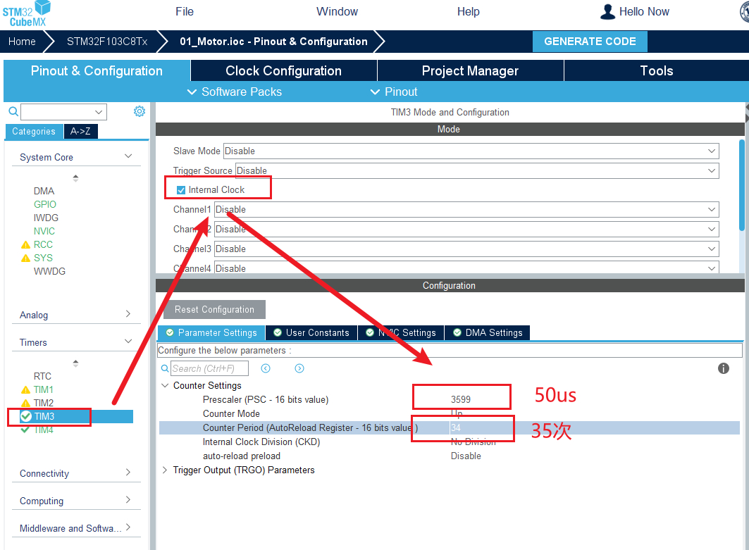
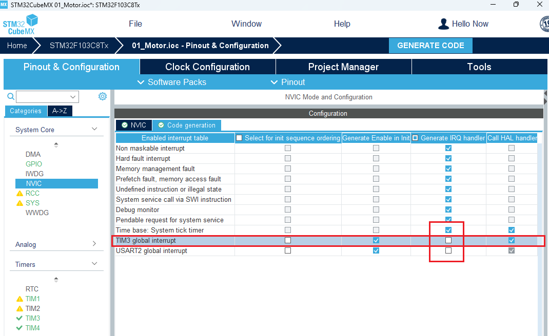
}6.1.3 定时器设置
① 说明
根据Modbus的时序可知,需要使用一个定时器判断传输数据是否超过3.5字符的时间,这里使用TIM3。
官方推荐定时器单次计数时间为50us,所以 PSC 为 3599,串口波特率大于 19200 时,可以直接使用固定 35 次来代替3.5字符的时间。
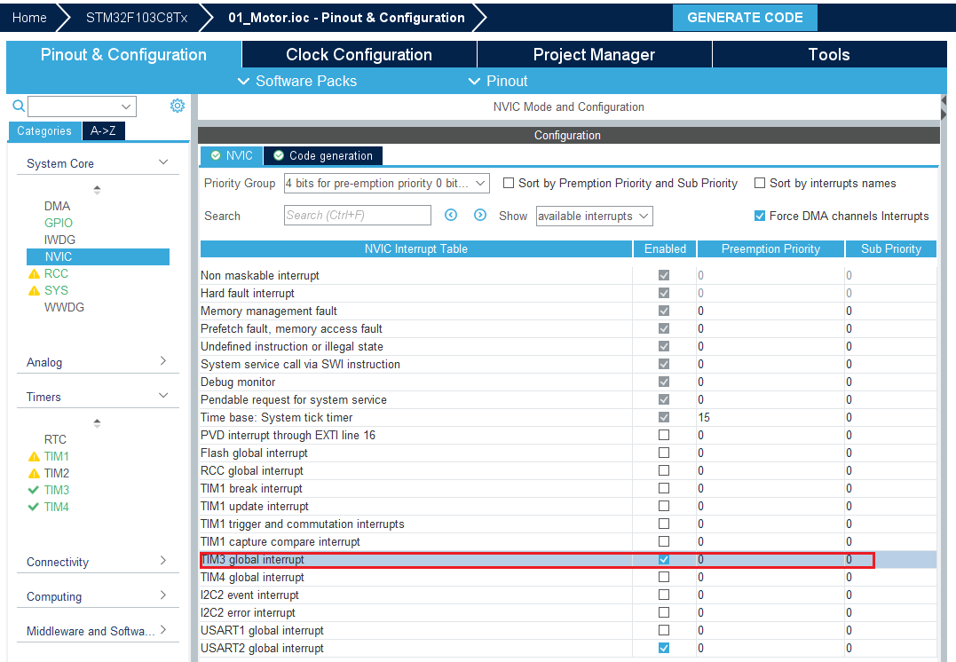
② CubeMX 配置
② 代码实现
FreeModbus/modbus/port.h
添加#include "tim.h"
FreeModbus/modbus/porttimer.c
/* ----------------------- Platform includes --------------------------------*/
#include "port.h"

/* ----------------------- Modbus includes ----------------------------------*/
#include "mb.h"
#include "mbport.h"

/* ----------------------- static functions ---------------------------------*/
static void prvvTIMERExpiredISR(void);

/* ----------------------- Start implementation -----------------------------*/
// 定时器初始化,HAL库生成的代码已经初始化,吧FALSE改为TRUE
BOOL xMBPortTimersInit(USHORT usTim1Timerout50us)
{
    // return FALSE;
    return TRUE;
}

// 启动定时器
inline void
vMBPortTimersEnable()
{
    /* Enable the timer with the timeout passed to xMBPortTimersInit( ) */
    // 清空定时器TIM3计数值
    __HAL_TIM_SET_COUNTER(&htim3, 0);

    // 启动定时器TIM3并开启更新中断
    HAL_TIM_Base_Start_IT(&htim3);
}

// 关闭定时器
inline void
vMBPortTimersDisable()
{
    /* Disable any pending timers. */
    // 关闭定时器TIM3更新中断
    HAL_TIM_Base_Stop_IT(&htim3);

}

/* Create an ISR which is called whenever the timer has expired. This function
 * must then call pxMBPortCBTimerExpired( ) to notify the protocol stack that
 * the timer has expired.
 */
// 无需修改,需要在中断服务函数中调用
static void prvvTIMERExpiredISR(void)
{
    (void)pxMBPortCBTimerExpired();
}

// 定义定时器TIM3的中断服务函数
void TIM3_IRQHandler(void)
{
    // 检查是否是定时器TIM3的更新中断
    if (__HAL_TIM_GET_FLAG(&htim3, TIM_FLAG_UPDATE))
    {
        // 清除中断标志位
        __HAL_TIM_CLEAR_FLAG(&htim3, TIM_FLAG_UPDATE);
        // 调用函数处理
        prvvTIMERExpiredISR();
    }

    // 调用HAL库提供处理定时器中断的逻辑的函数
    HAL_TIM_IRQHandler(&htim3);
}
6.1.4 四个核心回调函数实现
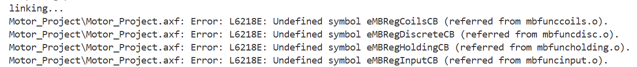
这个报错是因为 FreeModbus 协议栈所需的回调函数未在工程中定义,这些函数是Modbus从站设备必须实现的寄存器访问接口,用于处理主站对线圈、离散输入、保持寄存器和输入寄存器的读写请求。
四个核心回调函数及其作用
| 回调函数 | 对应寄存器类型 | 功能描述 |
|---|---|---|
eMBRegHoldingCB() | 保持寄存器(Holding Registers) | 处理保持寄存器的读写请求(功能码03/06/16),用于参数配置或数据存储。 |
eMBRegInputCB() | 输入寄存器(Input Registers) | 处理输入寄存器的读取请求(功能码04),通常用于返回传感器数据等只读值。 |
eMBRegCoilsCB() | 线圈寄存器(Coils) | 处理线圈寄存器的读写请求(功能码01/05/15),用于控制数字量输出设备。 |
eMBRegDiscreteCB() | 离散输入寄存器(Discrete Inputs) | 处理离散输入寄存器的读取请求(功能码02),返回开关量输入状态(如按钮信号)。 |
在 Mid/FreeModbus 下新建 Mid_Modbus.h 和 Mid_Modbus.c
Mid_FreeModbus.h
#ifndef __MID_FREEMODBUS_H__
#define __MID_FREEMODBUS_H__

#include "mb.h"
#include "mbport.h"

// 定义输入寄存器的数量
#define REG_INPUT_SIZE 10
// 声明输入寄存器缓冲区,用于存储十路输入寄存器的值
extern uint16_t REG_INPUT_BUF[REG_INPUT_SIZE];

// 定义保持寄存器的数量
#define REG_HOLD_SIZE 10
// 声明保持寄存器缓冲区,用于存储十路保持寄存器的值
extern uint16_t REG_HOLD_BUF[REG_HOLD_SIZE];

// 定义线圈的数量
#define REG_COILS_SIZE 10
// 声明线圈缓冲区,并初始化,用于存储十路线圈的状态
extern uint8_t REG_COILS_BUF[REG_COILS_SIZE];

// 定义离散量的数量
#define REG_DISC_SIZE 10
// 声明离散量缓冲区,并初始化,用于存储十路离散量的状态
extern uint8_t REG_DISC_BUF[REG_DISC_SIZE];

#endif /* __MID_FREEMODBUS_H__ */
Mid_FreeModbus.c
#include "Mid_FreeModbus.h"
// 准备使用[2]标示当前转速
// 声明输入寄存器缓冲区,用于存储输入寄存器的值
uint16_t REG_INPUT_BUF[REG_INPUT_SIZE]= {0, 0, 0, 0, 0, 0, 0, 0, 0, 0};
// 准备使用[2]标示目标转速
// 声明保持寄存器缓冲区,用于存储保持寄存器的值
uint16_t REG_HOLD_BUF[REG_HOLD_SIZE] = {0, 0, 0, 0, 0, 0, 0, 0, 0, 0};
// 准备使用[2]标示电机的启动和停止
// 声明线圈缓冲区,用于保存线圈的状态
uint8_t REG_COILS_BUF[REG_COILS_SIZE] = {0, 0, 0, 0, 0, 0, 0, 0, 0, 0};
// 准备使用[2]标示电机的方向
// 声明离散量缓冲区,并初始化,用于存储离散量的状态
uint8_t REG_DISC_BUF[REG_DISC_SIZE] = {0, 0, 0, 0, 0, 0, 0, 0, 0, 0};
/**
* @brief 功能码04 处理回调函数
*
* 该函数用于处理MODBUS协议中的CMD4命令,即读取输入寄存器。
* 它将指定地址范围内的输入寄存器的值复制到缓冲区中。
*
* @param pucRegBuffer 指向用于存储寄存器值的缓冲区的指针。
* @param usAddress 要读取的起始寄存器地址。
* @param usNRegs 要读取的寄存器数量。
*
* @return 返回执行结果的错误代码。
*/
eMBErrorCode eMBRegInputCB(UCHAR *pucRegBuffer, USHORT usAddress, USHORT usNRegs)
{
// 计算寄存器索引,从0开始
USHORT usRegIndex = usAddress - 1;
// 非法检测:检查访问范围是否超出寄存器缓冲区大小
if ((usRegIndex + usNRegs) > REG_INPUT_SIZE)
{
return MB_ENOREG;
}
// 循环读取寄存器值并写入缓冲区
while (usNRegs > 0)
{
// 将寄存器的高8位写入缓冲区
*pucRegBuffer++ = (unsigned char)(REG_INPUT_BUF[usRegIndex] >> 8);
// 将寄存器的低8位写入缓冲区
*pucRegBuffer++ = (unsigned char)(REG_INPUT_BUF[usRegIndex] & 0xFF);
usRegIndex++;
usNRegs--;
}
return MB_ENOERR;
}
/**
* @brief 功能码06、03、16 处理回调函数
*
* 该函数用于处理Modbus协议中的 Holding Registers 读写请求。
* 它根据请求的模式(读或写)对指定的寄存器进行相应的操作。
*
* @param pucRegBuffer 寄存器数据缓冲区,用于读取或写入寄存器数据。
* @param usAddress 请求访问的起始寄存器地址。
* @param usNRegs 请求访问的寄存器数量。
* @param eMode 访问模式,可以是 MB_REG_WRITE(写寄存器)或 MB_REG_READ(读寄存器)。
*
* @return 返回执行结果,如果成功则返回 MB_ENOERR,否则返回相应的错误代码。
*/
eMBErrorCode eMBRegHoldingCB(UCHAR *pucRegBuffer, USHORT usAddress, USHORT usNRegs, eMBRegisterMode eMode)
{
// 计算寄存器索引,Modbus 地址从 1 开始,数组索引从 0 开始,因此需要减 1。
USHORT usRegIndex = usAddress - 1;
// 非法检测:检查访问范围是否超出寄存器缓冲区大小。
if ((usRegIndex + usNRegs) > REG_HOLD_SIZE)
{
return MB_ENOREG;
}
// 写寄存器
if (eMode == MB_REG_WRITE)
{
// 循环将每个寄存器的数据从缓冲区写入到寄存器中。
while (usNRegs > 0)
{
REG_HOLD_BUF[usRegIndex] = (pucRegBuffer[0] << 8) | pucRegBuffer[1];
pucRegBuffer += 2;
usRegIndex++;
usNRegs--;
}
}
// 读寄存器
else
{
// 循环将每个寄存器的数据从寄存器中读取到缓冲区。
while (usNRegs > 0)
{
*pucRegBuffer++ = (unsigned char)(REG_HOLD_BUF[usRegIndex] >> 8);
*pucRegBuffer++ = (unsigned char)(REG_HOLD_BUF[usRegIndex] & 0xFF);
usRegIndex++;
usNRegs--;
}
}
return MB_ENOERR;
}
/**
* @brief 功能码01、05、15 处理回调函数
*
* 该函数用于处理Modbus协议中的CMD1、CMD5和CMD15命令。
* 它主要负责读取或写入寄存器中的位数据。
*
* @param pucRegBuffer 指向寄存器缓冲区的指针,用于读取或写入数据。
* @param usAddress 要操作的寄存器起始地址。
* @param usNCoils 要操作的位数。
* @param eMode 操作模式,可以是读或写。
*
* @return 返回操作结果,如果成功则返回MB_ENOERR,否则返回相应的错误代码。
*/
eMBErrorCode eMBRegCoilsCB(UCHAR *pucRegBuffer, USHORT usAddress, USHORT usNCoils, eMBRegisterMode eMode)
{
// 计算寄存器索引
USHORT usRegIndex = usAddress - 1;
// 用于位操作的变量
UCHAR ucBits = 0;
// 用于存储位状态的变量
UCHAR ucState = 0;
// 用于循环操作的变量
UCHAR ucLoops = 0;
// 非法检测:检查访问范围是否超出寄存器缓冲区大小。
if ((usRegIndex + usNCoils) > REG_COILS_SIZE)
{
return MB_ENOREG;
}
// 根据操作模式执行相应的操作
if (eMode == MB_REG_WRITE)
{
// 计算需要循环的次数
ucLoops = (usNCoils - 1) / 8 + 1;
// 写操作
while (ucLoops != 0)
{
// 获取当前寄存器的状态
ucState = *pucRegBuffer++;
// 位操作
ucBits = 0;
// 遍历每个位
while (usNCoils != 0 && ucBits < 8)
{
// 将状态写入寄存器缓冲区
REG_COILS_BUF[usRegIndex++] = (ucState >> ucBits) & 0X01;
// 更新剩余位数
usNCoils--;
// 更新位索引
ucBits++;
}
// 更新循环次数
ucLoops--;
}
}
else
{
// 计算需要循环的次数
ucLoops = (usNCoils - 1) / 8 + 1;
// 读操作
while (ucLoops != 0)
{
// 初始化状态变量
ucState = 0;
// 位操作
ucBits = 0;
// 遍历每个位
while (usNCoils != 0 && ucBits < 8)
{
// 根据寄存器缓冲区的状态更新状态变量
if (REG_COILS_BUF[usRegIndex])
{
ucState |= (1 << ucBits);
}
// 更新剩余位数
usNCoils--;
// 更新寄存器索引
usRegIndex++;
// 更新位索引
ucBits++;
}
// 将状态写入寄存器缓冲区
*pucRegBuffer++ = ucState;
// 更新循环次数
ucLoops--;
}
}
return MB_ENOERR;
}
/**
* @brief 功能码02 处理回调函数
*
* 该函数用于处理MODBUS协议中的CMD2命令,主要负责读取离散输入寄存器的值。
*
* @param pucRegBuffer 指向存放寄存器数据的缓冲区。
* @param usAddress 寄存器的起始地址。
* @param usNDiscrete 要读取的离散输入寄存器的数量。
*
* @return 返回执行结果,如果成功则返回MB_ENOERR,否则返回相应的错误代码。
*/
eMBErrorCode eMBRegDiscreteCB(UCHAR *pucRegBuffer, USHORT usAddress, USHORT usNDiscrete)
{
// 计算寄存器索引,从0开始
USHORT usRegIndex = usAddress - 1;
// 用于处理位操作的变量
UCHAR ucBits = 0;
// 用于存储当前寄存器状态的变量
UCHAR ucState = 0;
// 用于控制循环次数的变量
UCHAR ucLoops = 0;
// 非法检测:检查访问范围是否超出寄存器缓冲区大小
if ((usRegIndex + usNDiscrete) > REG_DISC_SIZE)
{
return MB_ENOREG;
}
// 计算需要循环的次数,每次循环处理最多8个离散输入
ucLoops = (usNDiscrete - 1) / 8 + 1;
// 循环读取离散输入寄存器的值
while (ucLoops != 0)
{
ucState = 0;
ucBits = 0;
// 读取每个寄存器的值,并将其状态更新到ucState变量中
while (usNDiscrete != 0 && ucBits < 8)
{
if (REG_DISC_BUF[usRegIndex])
{
ucState |= (1 << ucBits);
}
usNDiscrete--;
usRegIndex++;
ucBits++;
}
// 将读取到的状态值存入缓冲区中
*pucRegBuffer++ = ucState;
ucLoops--;
}
// 模拟离散量输入被改变,这里简单地将每个寄存器的状态取反
for (usRegIndex = 0; usRegIndex < REG_DISC_SIZE; usRegIndex++)
{
REG_DISC_BUF[usRegIndex] = !REG_DISC_BUF[usRegIndex];
}
return MB_ENOERR;
}
/**
* @brief 将 Modbus 库错误码映射为 Modbus 异常码
*
* @param error Modbus 库错误码(eMBErrorCode)
* @return 对应的 Modbus 异常码
*/
uint8_t mapErrorToException(eMBErrorCode error)
{
switch (error)
{
case MB_ENOREG: // 非法寄存器地址
return 0x02; // 非法数据地址
case MB_EINVAL: // 非法参数
return 0x03; // 非法数据值
case MB_ENORES: // 资源不足
return 0x04; // 从站设备故障
case MB_ETIMEDOUT: // 超时
return 0x06; // 从站设备忙
case MB_EPORTERR: // 端口错误
return 0x04; // 从站设备故障
case MB_ENOERR: // 无错误
return 0x00; // 无异常
default: // 未知错误
return 0x04; // 从站设备故障
}
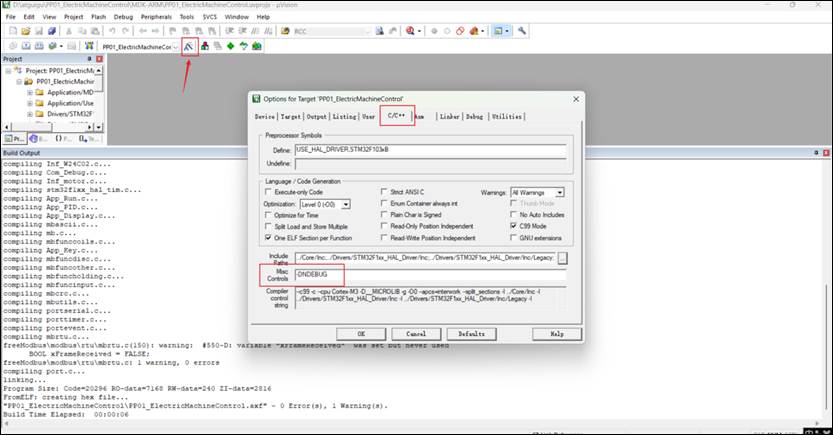
}6.1.5 去除断言依赖
此时编译代码会报错:
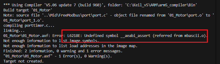
进入keil软件中,在C/C++栏中添加-DNDEBUG字段,去除断言依赖:
6.2 Modbus 通信测试
6.2.1 电机项目: 发送测试
① Modubs 应用模块
App_Modbus.h
添加头文件包含和函数原型:
#include "Mid_FreeModbus.h"

/**
 * @brief 初始化Modubs应用
 *
 */
void App_Modubs_Init(void);

/**
 * @brief 轮询接收主机的Modbus数据
 *
 */
void App_Modbus_ReceivePoll(void);
App_Modbus.c
添加函数定义:
/**
 * @brief 初始化Modubs应用
 *
 */
void App_Modubs_Init(void)
{
    printf("Modbusid: %d \n", g_modbus_id);
    // 初始化 Modbus 协议栈
    // 参数1:Modbus 模式(RTU);参数2: 从站地址;参数3: 串口编号(这里随便设置,内部已经写死使用USART2);参数4: 波特率(随便设置,HAL库中已经选择了115200); 参数5: 无校验
    eMBInit(MB_RTU, g_modbus_id, 0, 115200, MB_PAR_NONE) == MB_ENOERR ? printf("Modubs 协议栈初始化成功! \n") : printf("Modubs 协议栈初始化失败! \n");

    // 使能 Modbus 协议栈
    eMBEnable() == MB_ENOERR ? printf("Modubs 协议栈使能成功! \n") : printf("Modubs 协议栈使能失败! \n");

}

/**
 * @brief 轮询接收主机的Modbus数据
 *
 */
void App_Modbus_ReceivePoll(void)
{
    // 轮询调用接收Modbus数据
    eMBPoll();
}
② Modubs 任务
App_Task.c
添加 modbus 任务:
注意: Modbus管理任务优先级要小于ModbusID管理任务,因为要先获取ModbusID!
/* 代码省略 ... */

// Modbus 管理任务 ------------------------------------
// Modbus管理任务函数的原型
void modubs_task_callback(void *pvParameters);
// Modbus管理任务名称
#define MODUBS_TASK_NAME "modubs_task"
// Modbus管理任务堆栈大小
#define MODUBS_TASK_STACK_SIZE 512
// Modbus管理任务的优先级, 优先级需要小于ModbusID管理任务的优先级,因为要先获取ModbusID
#define MODUBS_TASK_PRIORITY 3
// 任务4的句柄
TaskHandle_t modubs_task_handle;

/**
 * @brief 启动FreeRTOS
 *
 */
void App_TASK_Start(void)
{
    /* 代码省略 ... */

    // 创建Modbus管理任务
    xTaskCreate(modubs_task_callback, MODUBS_TASK_NAME, MODUBS_TASK_STACK_SIZE, NULL, MODUBS_TASK_PRIORITY, &modubs_task_handle) == pdPASS ? printf("Modbus管理任务创建成功! \n") : printf("Modbus管理任务创建失败! \n");

	/* 代码省略 ... */
}

/* 代码省略 ... */

// Modbus管理任务函数的实现
void modubs_task_callback(void *pvParameters)
{
    printf("Modbus管理任务启动... \n");

    // 初始化Modbus应用
    App_Modubs_Init();

    while (1)
    {
        // 轮询接收Modbus报文
        App_Modbus_ReceivePoll();

        // 阻塞延时
        vTaskDelay(50);
    }
}

/* 代码省略 ... */
③ 接收测试代码
在 mbrtu.c 文件的 eMBRTUReceive 函数内添加测试代码:
// 接收测试
DEBUG_PRINTLN("接收到报文------------");
DEBUG_PRINTLN("报文长度: %d", usRcvBufferPos);
DEBUG_PRINTF("报文内容: ");
for (int i = 0; i < usRcvBufferPos; i++)
{
    printf("0x%02X ", ucRTUBuf[i]);
}
DEBUG_PRINTF("\n\n");
6.2.2 网关项目: 发送测试
① 原理图
② CubeMX 配置
③ 发送测试测代
main.c 中的 main 函数中:
DEBUG_PRINTLN("Modbus 发送测试...");
// 定义要发送的报文,读线圈报文
uint8_t read1[8] = {0x05, 0x01, 0x00, 0x02, 0x00, 0x01, 0x5D, 0x8E};
// 打印Modbus报文
DEBUG_PRINTLN("报文长度: %d", 8);
DEBUG_PRINTF("报文内容: ");
for (uint16_t i = 0; i < 8; i++)
{
    printf("0x%02X ", read1[i]);
}
printf("\n\n");
// 帧间隔时间
HAL_Delay(100);
// 使用串口发送
HAL_UART_Transmit(&huart2, read1, 8, HAL_MAX_DELAY);
6.3 网关项目: 主机 Modbus 通信实现
6.3.1 网关项目:封装读写线圈操作以及其他寄存器操作
① 公共层:移植CRC
移植电机项目中的 Mid/FreeModbus/modbus/rtu 中的 mbcrc.h 和 mbcrc.c
Com_MBCRC.h
#ifndef _MB_CRC_H
#define _MB_CRC_H

#include <stdint.h>

uint16_t          usMBCRC16( uint8_t * pucFrame, uint16_t usLen );


#endif
Com_MBCRC.c
/* ----------------------- Platform includes --------------------------------*/
#include "Com_MBCRC.h"

static const uint8_t aucCRCHi[] = {
    0x00, 0xC1, 0x81, 0x40, 0x01, 0xC0, 0x80, 0x41, 0x01, 0xC0, 0x80, 0x41,
    0x00, 0xC1, 0x81, 0x40, 0x01, 0xC0, 0x80, 0x41, 0x00, 0xC1, 0x81, 0x40,
    0x00, 0xC1, 0x81, 0x40, 0x01, 0xC0, 0x80, 0x41, 0x01, 0xC0, 0x80, 0x41,
    0x00, 0xC1, 0x81, 0x40, 0x00, 0xC1, 0x81, 0x40, 0x01, 0xC0, 0x80, 0x41,
    0x00, 0xC1, 0x81, 0x40, 0x01, 0xC0, 0x80, 0x41, 0x01, 0xC0, 0x80, 0x41,
    0x00, 0xC1, 0x81, 0x40, 0x01, 0xC0, 0x80, 0x41, 0x00, 0xC1, 0x81, 0x40,
    0x00, 0xC1, 0x81, 0x40, 0x01, 0xC0, 0x80, 0x41, 0x00, 0xC1, 0x81, 0x40,
    0x01, 0xC0, 0x80, 0x41, 0x01, 0xC0, 0x80, 0x41, 0x00, 0xC1, 0x81, 0x40,
    0x00, 0xC1, 0x81, 0x40, 0x01, 0xC0, 0x80, 0x41, 0x01, 0xC0, 0x80, 0x41,
    0x00, 0xC1, 0x81, 0x40, 0x01, 0xC0, 0x80, 0x41, 0x00, 0xC1, 0x81, 0x40,
    0x00, 0xC1, 0x81, 0x40, 0x01, 0xC0, 0x80, 0x41, 0x01, 0xC0, 0x80, 0x41,
    0x00, 0xC1, 0x81, 0x40, 0x00, 0xC1, 0x81, 0x40, 0x01, 0xC0, 0x80, 0x41,
    0x00, 0xC1, 0x81, 0x40, 0x01, 0xC0, 0x80, 0x41, 0x01, 0xC0, 0x80, 0x41,
    0x00, 0xC1, 0x81, 0x40, 0x00, 0xC1, 0x81, 0x40, 0x01, 0xC0, 0x80, 0x41,
    0x01, 0xC0, 0x80, 0x41, 0x00, 0xC1, 0x81, 0x40, 0x01, 0xC0, 0x80, 0x41,
    0x00, 0xC1, 0x81, 0x40, 0x00, 0xC1, 0x81, 0x40, 0x01, 0xC0, 0x80, 0x41,
    0x00, 0xC1, 0x81, 0x40, 0x01, 0xC0, 0x80, 0x41, 0x01, 0xC0, 0x80, 0x41,
    0x00, 0xC1, 0x81, 0x40, 0x01, 0xC0, 0x80, 0x41, 0x00, 0xC1, 0x81, 0x40,
    0x00, 0xC1, 0x81, 0x40, 0x01, 0xC0, 0x80, 0x41, 0x01, 0xC0, 0x80, 0x41,
    0x00, 0xC1, 0x81, 0x40, 0x00, 0xC1, 0x81, 0x40, 0x01, 0xC0, 0x80, 0x41,
    0x00, 0xC1, 0x81, 0x40, 0x01, 0xC0, 0x80, 0x41, 0x01, 0xC0, 0x80, 0x41,
    0x00, 0xC1, 0x81, 0x40
};

static const uint8_t aucCRCLo[] = {
    0x00, 0xC0, 0xC1, 0x01, 0xC3, 0x03, 0x02, 0xC2, 0xC6, 0x06, 0x07, 0xC7,
    0x05, 0xC5, 0xC4, 0x04, 0xCC, 0x0C, 0x0D, 0xCD, 0x0F, 0xCF, 0xCE, 0x0E,
    0x0A, 0xCA, 0xCB, 0x0B, 0xC9, 0x09, 0x08, 0xC8, 0xD8, 0x18, 0x19, 0xD9,
    0x1B, 0xDB, 0xDA, 0x1A, 0x1E, 0xDE, 0xDF, 0x1F, 0xDD, 0x1D, 0x1C, 0xDC,
    0x14, 0xD4, 0xD5, 0x15, 0xD7, 0x17, 0x16, 0xD6, 0xD2, 0x12, 0x13, 0xD3,
    0x11, 0xD1, 0xD0, 0x10, 0xF0, 0x30, 0x31, 0xF1, 0x33, 0xF3, 0xF2, 0x32,
    0x36, 0xF6, 0xF7, 0x37, 0xF5, 0x35, 0x34, 0xF4, 0x3C, 0xFC, 0xFD, 0x3D,
    0xFF, 0x3F, 0x3E, 0xFE, 0xFA, 0x3A, 0x3B, 0xFB, 0x39, 0xF9, 0xF8, 0x38,
    0x28, 0xE8, 0xE9, 0x29, 0xEB, 0x2B, 0x2A, 0xEA, 0xEE, 0x2E, 0x2F, 0xEF,
    0x2D, 0xED, 0xEC, 0x2C, 0xE4, 0x24, 0x25, 0xE5, 0x27, 0xE7, 0xE6, 0x26,
    0x22, 0xE2, 0xE3, 0x23, 0xE1, 0x21, 0x20, 0xE0, 0xA0, 0x60, 0x61, 0xA1,
    0x63, 0xA3, 0xA2, 0x62, 0x66, 0xA6, 0xA7, 0x67, 0xA5, 0x65, 0x64, 0xA4,
    0x6C, 0xAC, 0xAD, 0x6D, 0xAF, 0x6F, 0x6E, 0xAE, 0xAA, 0x6A, 0x6B, 0xAB,
    0x69, 0xA9, 0xA8, 0x68, 0x78, 0xB8, 0xB9, 0x79, 0xBB, 0x7B, 0x7A, 0xBA,
    0xBE, 0x7E, 0x7F, 0xBF, 0x7D, 0xBD, 0xBC, 0x7C, 0xB4, 0x74, 0x75, 0xB5,
    0x77, 0xB7, 0xB6, 0x76, 0x72, 0xB2, 0xB3, 0x73, 0xB1, 0x71, 0x70, 0xB0,
    0x50, 0x90, 0x91, 0x51, 0x93, 0x53, 0x52, 0x92, 0x96, 0x56, 0x57, 0x97,
    0x55, 0x95, 0x94, 0x54, 0x9C, 0x5C, 0x5D, 0x9D, 0x5F, 0x9F, 0x9E, 0x5E,
    0x5A, 0x9A, 0x9B, 0x5B, 0x99, 0x59, 0x58, 0x98, 0x88, 0x48, 0x49, 0x89,
    0x4B, 0x8B, 0x8A, 0x4A, 0x4E, 0x8E, 0x8F, 0x4F, 0x8D, 0x4D, 0x4C, 0x8C,
    0x44, 0x84, 0x85, 0x45, 0x87, 0x47, 0x46, 0x86, 0x82, 0x42, 0x43, 0x83,
    0x41, 0x81, 0x80, 0x40
};

uint16_t
usMBCRC16( uint8_t * pucFrame, uint16_t usLen )
{
    uint8_t           ucCRCHi = 0xFF;
    uint8_t           ucCRCLo = 0xFF;
    int             iIndex;

    while( usLen-- )
    {
        iIndex = ucCRCLo ^ *( pucFrame++ );
        ucCRCLo = ( uint8_t )( ucCRCHi ^ aucCRCHi[iIndex] );
        ucCRCHi = aucCRCLo[iIndex];
    }
    return ( uint16_t )( ucCRCHi << 8 | ucCRCLo );
}
② 中间层:实现 Modubs 读写从机寄存器操作
Mid_Modbus.h
#ifndef __MID_MODBUS_H__
#define __MID_MODBUS_H__

#include "usart.h"

#include "FreeRTOS.h"
#include "portable.h"

#include "Com_Debug.h"
#include "Com_MBCRC.h"

/**
 * @brief 读取Modbus线圈状态
 *
 * @param slave_addr 从站地址
 * @param start_addr 起始地址
 * @param num_coils  线圈数量
 */
void Mid_Modbus_ReadCoil(uint8_t slave_addr, uint16_t start_addr, uint16_t num_coils);


/**
 * @brief  读离散输入
 *
 * @param slave_addr 从站地址
 * @param start_addr 起始地址
 * @param num        数量
 */
void Mid_Modbus_ReadDiscreteInput(uint8_t slave_addr,  uint16_t start_addr, uint16_t num);


/**
 * @brief  读保持寄存器
 *
 * @param slave_addr 从站地址
 * @param start_addr 起始地址
 * @param num        数量
 */
void Mid_Modbus_ReadHoldingReg(uint8_t slave_addr,  uint16_t start_addr, uint16_t num);


/**
 * @brief  读输入寄存器
 *
 * @param slave_addr 从站地址
 * @param start_addr 起始地址
 * @param num        数量
 */
void Mid_Modbus_ReadInputReg(uint8_t slave_addr,  uint16_t start_addr,uint16_t num);


/**
 * @brief 写入Modbus单个线圈状态
 *
 * @param slave_addr 从站地址
 * @param coil_addr  线圈地址
 * @param coil_status 线圈状态(0或1)
 */
void Mid_Modbus_WriteCoil(uint8_t slave_addr, uint16_t coil_addr, uint8_t coil_status);

/**
 * @brief  写单个保持寄存器
 *
 * @param slave_addr 从站地址
 * @param start_addr 起始地址
 * @param value      寄存器值

 */
void Mid_Modbus_WriteHoldingReg(uint8_t slave_addr,  uint16_t start_addr,  uint16_t value);

/**
 * @brief  写多个线圈
 *
 * @param slave_addr 从站地址
 * @param start_addr 起始地址
 * @param num        数量
 * @param value      线圈状态数组
 */
void Mid_Modbus_WriteCoils(uint8_t slave_addr,  uint16_t start_addr, uint16_t num, uint8_t *value);

/**
 * @brief  写多个保持寄存器 按字节数组写入
 *
 * @param slave_addr 从站地址
 * @param start_addr 起始地址
 * @param data       数据数组
 * @param len        数据长度
 */
void Mid_Modbus_WriteHoldingRegs(uint8_t slave_addr,  uint16_t start_addr, uint16_t *data ,uint16_t len);

#endif /* __MID_MODBUS_H__ */
Mid_Modbus.c
#include "Mid_Modbus.h"

// 静态函数:发送Modbus报文
static void Mid_Modbus_Send(uint8_t *tx_data, uint16_t tx_len)
{
    DEBUG_PRINTLN("发送Modbus报文--------");
    DEBUG_PRINTLN("报文长度: %d", tx_len);
    DEBUG_PRINTF("报文内容: ");
    for (uint16_t i = 0; i < tx_len; i++)
    {
        printf("0x%02X ", tx_data[i]);
    }
    printf("\n\n");

    // 延时10ms,作为帧间隔时间(帧前静默时间)
    HAL_Delay(10);

    // 调用USART2发送数据
    HAL_UART_Transmit(&huart2, tx_data, tx_len, HAL_MAX_DELAY);
}

/**
 * @brief 读取Modbus线圈状态
 *
 * @param slave_addr 从站地址
 * @param start_addr 起始地址
 * @param num_coils  线圈数量
 */
void Mid_Modbus_ReadCoil(uint8_t slave_addr, uint16_t start_addr, uint16_t num_coils)
{
    // 1. 定义数组,作为Modbus读取线圈的报文
    uint8_t tx_bytes[8];

    // 2. 组装报文
    // 2.1 从设备地址
    tx_bytes[0] = slave_addr;
    // 2.2 功能码:读取线圈状态
    tx_bytes[1] = 0x01;
    // 2.3 线圈起始地址
    tx_bytes[2] = (start_addr >> 8) & 0xFF; // 高字节
    tx_bytes[3] = start_addr & 0xFF;        // 低字节
    // 2.4 线圈数量
    tx_bytes[4] = (num_coils >> 8) & 0xFF; // 高字节
    tx_bytes[5] = num_coils & 0xFF;        // 低字节
    // 2.5 校验码,使用前6个字节计算校验码(先发低字节再发高字节),
    uint16_t crc = usMBCRC16(tx_bytes, 6);
    tx_bytes[6] = crc & 0xFF;        // 低字节
    tx_bytes[7] = (crc >> 8) & 0xFF; // 高字节

    // 3. 发送Modbus读取线圈状态的报文
    Mid_Modbus_Send(tx_bytes, 8);
}

/**
 * @brief  读离散输入
 *
 * @param slave_addr 从站地址
 * @param start_addr 起始地址
 * @param num        数量
 */
void Mid_Modbus_ReadDiscreteInput(uint8_t slave_addr, uint16_t start_addr, uint16_t num)
{
    uint8_t cmd[8] = {0};

    cmd[0] = slave_addr;
    cmd[1] = 0x02; // 功能码
    cmd[2] = (start_addr >> 8) & 0xff;
    cmd[3] = (start_addr >> 0) & 0xff;
    cmd[4] = (num >> 8) & 0xff;
    cmd[5] = (num >> 0) & 0xff;
    // CRC校验
    uint16_t crc = usMBCRC16(cmd, 6);
    cmd[6] = (crc >> 0) & 0xff;
    cmd[7] = (crc >> 8) & 0xff;

    Mid_Modbus_Send(cmd, 8);
}

/**
 * @brief  读保持寄存器
 *
 * @param slave_addr 从站地址
 * @param start_addr 起始地址
 * @param num        数量
 */
void Mid_Modbus_ReadHoldingReg(uint8_t slave_addr, uint16_t start_addr, uint16_t num)
{
    uint8_t cmd[8] = {0};
    cmd[0] = slave_addr;
    cmd[1] = 0x03; // 功能码
    cmd[2] = (start_addr >> 8) & 0xff;
    cmd[3] = (start_addr >> 0) & 0xff;
    cmd[4] = (num >> 8) & 0xff;
    cmd[5] = (num >> 0) & 0xff;

    // CRC校验
    uint16_t crc = usMBCRC16(cmd, 6);
    cmd[6] = (crc >> 0) & 0xff;
    cmd[7] = (crc >> 8) & 0xff;

    Mid_Modbus_Send(cmd, 8);
}

/**
 * @brief  读输入寄存器
 *
 * @param slave_addr 从站地址
 * @param start_addr 起始地址
 * @param num        数量
 */
void Mid_Modbus_ReadInputReg(uint8_t slave_addr, uint16_t start_addr, uint16_t num)
{
    uint8_t cmd[8] = {0};
    cmd[0] = slave_addr;
    cmd[1] = 0x04; // 功能码
    cmd[2] = (start_addr >> 8) & 0xff;
    cmd[3] = (start_addr >> 0) & 0xff;
    cmd[4] = (num >> 8) & 0xff;
    cmd[5] = (num >> 0) & 0xff;

    // CRC校验
    uint16_t crc = usMBCRC16(cmd, 6);
    cmd[6] = (crc >> 0) & 0xff;
    cmd[7] = (crc >> 8) & 0xff;

    Mid_Modbus_Send(cmd, 8);
}

/**
 * @brief 写入Modbus单个线圈状态
 *
 * @param slave_addr 从站地址
 * @param coil_addr  线圈地址
 * @param coil_status 线圈状态(0或1)
 */
void Mid_Modbus_WriteCoil(uint8_t slave_addr, uint16_t coil_addr, uint8_t coil_status)
{
    // 1. 定义数组,作为Modbus写入单个线圈状态的报文
    uint8_t tx_bytes[8];

    // 2. 阻值Modbus写入单个线圈的报文
    // 2.1 从设备地址
    tx_bytes[0] = slave_addr;
    // 2.2 功能码:写入单个线圈状态
    tx_bytes[1] = 0x05;
    // 2.3 线圈地址
    tx_bytes[2] = (coil_addr >> 8) & 0xFF; // 高字节
    tx_bytes[3] = coil_addr & 0xFF;        // 低字节
    // 2.4 线圈状态
    if (coil_status)
    {
        // 线圈状态为1,设置高字节为0xFFFF
        tx_bytes[4] = 0xFF;
    }
    else
    {
        // 线圈状态为0,设置高字节为0x0000
        tx_bytes[4] = 0x00;
    }
    tx_bytes[5] = 0x00;
    // 2.5 校验码,使用前6个字节计算校验码(先发低字节再发高字节),
    uint16_t crc = usMBCRC16(tx_bytes, 6);
    tx_bytes[6] = crc & 0xFF;        // 低字节
    tx_bytes[7] = (crc >> 8) & 0xFF; // 高字节

    // 3. 发送Modbus写入单个线圈状态的报文
    Mid_Modbus_Send(tx_bytes, 8);
}

/**
 * @brief  写单个保持寄存器
 *
 * @param slave_addr 从站地址
 * @param start_addr 起始地址
 * @param value      寄存器值

 */
void Mid_Modbus_WriteHoldingReg(uint8_t slave_addr, uint16_t start_addr, uint16_t value)
{
    uint8_t cmd[8] = {0};
    cmd[0] = slave_addr;
    cmd[1] = 0x06; // 功能码
    cmd[2] = (start_addr >> 8) & 0xff;
    cmd[3] = (start_addr >> 0) & 0xff;
    cmd[4] = (value >> 8) & 0xff;
    cmd[5] = (value >> 0) & 0xff;

    // CRC校验
    uint16_t crc = usMBCRC16(cmd, 6);
    cmd[6] = (crc >> 0) & 0xff;
    cmd[7] = (crc >> 8) & 0xff;

    Mid_Modbus_Send(cmd, 8);
}

/**
 * @brief  写多个线圈
 *
 * @param slave_addr 从站地址
 * @param start_addr 起始地址
 * @param num        数量
 * @param value      线圈状态数组
 */
void Mid_Modbus_WriteCoils(uint8_t slave_addr, uint16_t start_addr, uint16_t num, uint8_t *value)
{
    /* 思路分析
        需要写入的数据: 101010101
        数量: 9
        字节数: 2
        数据字节1: 01010101
        数据字节2: 00000001
        1. 计算字节数: 根据num计算
        */

    // 计算字节数
    uint8_t bytes_num = num % 8 == 0 ? num / 8 : num / 8 + 1;
    // 计算总长度
    uint8_t total_num = bytes_num + 9;

    // uint8_t cmd[total_num] = {0};
    uint8_t *cmd = pvPortMalloc(total_num);
    cmd[0] = slave_addr;
    cmd[1] = 0x0F; // 功能码
    cmd[2] = (start_addr >> 8) & 0xff;
    cmd[3] = (start_addr >> 0) & 0xff;
    cmd[4] = (num >> 8) & 0xff;
    cmd[5] = (num >> 0) & 0xff;
    cmd[6] = bytes_num;
    /*
      需要写入的数据value: 111010101
      数据字节1: 01010111
      数据字节2: 00000001

    */

    for (uint8_t i = 0; i < bytes_num; i++)
    {
        uint8_t data = 0;
        for (uint8_t j = 0; j < 8; j++)
        {
            /*
              j: 0 ===>   value[j] ===> 1 ===> data |= 0000 0001
              j: 1 ===>   value[j] ===> 1 ===> data |= 0000 0010
              j: 2 ===>   value[j] ===> 1 ===> data |= 0000 0100
              j: 3 ===>   value[j] ===> 0 ===> data |= 0000 0000
              data: 0000 0111
            */

            data |= value[j + 8 * i] << j;
        }
        cmd[7 + i] = data;
    }

    // CRC校验
    uint16_t crc = usMBCRC16(cmd, total_num - 2);
    cmd[total_num - 2] = (crc >> 0) & 0xff;
    cmd[total_num - 1] = (crc >> 8) & 0xff;

    Mid_Modbus_Send(cmd, total_num);

    // 主动释放mall手动分配的内存
    vPortFree(cmd);
}

/**
 * @brief  写多个保持寄存器 按字节数组写入
 *
 * @param slave_addr 从站地址
 * @param start_addr 起始地址
 * @param data       数据数组
 * @param len        数据长度
 */
void Mid_Modbus_WriteHoldingRegs(uint8_t slave_addr, uint16_t start_addr, uint16_t *data, uint16_t len)
{
    // 计算字节数
    uint8_t bytes_num = len * 2;
    // 计算总长度
    uint8_t total_num = bytes_num + 9;

    uint8_t *cmd = pvPortMalloc(total_num);
    cmd[0] = slave_addr;
    cmd[1] = 0x10; // 功能码
    cmd[2] = (start_addr >> 8) & 0xff;
    cmd[3] = (start_addr >> 0) & 0xff;
    cmd[4] = (len >> 8) & 0xff;
    cmd[5] = (len >> 0) & 0xff;
    cmd[6] = bytes_num;
    /*
      需要写入的数据value: 111010101
      数据字节1: 01010111
      数据字节2: 00000001

    */
    // {0x1234, 0xABCD}
    for (uint8_t i = 0; i < len; i++)
    {
        cmd[7 + i * 2] = (data[i] >> 8) & 0xff;
        cmd[8 + i * 2] = (data[i] >> 0) & 0xff;
    }

    // CRC校验
    uint16_t crc = usMBCRC16(cmd, total_num - 2);
    cmd[total_num - 2] = (crc >> 0) & 0xff;
    cmd[total_num - 1] = (crc >> 8) & 0xff;

    Mid_Modbus_Send(cmd, total_num);

    // 主动释放mall手动分配的内存
    vPortFree(cmd);
}
④ 读写线圈测试
网关项目中
main.c 中的 main 函数中
// 写线圈操作
HAL_Delay(100); // 从机的Modbus接收任务会阻塞10ms,而且相对的延时阻塞
DEBUG_PRINTLN("写线圈操作...");
Mid_Modbus_WriteCoil(0x05, 2, 1);

// 读线圈操作
HAL_Delay(100); // 从机的Modbus接收任务会阻塞10ms,而且相对的延时阻塞
DEBUG_PRINTLN("读线圈操作...");
Mid_Modbus_ReadCoil(0x05, 2, 1);
电机项目中
Mid_FreeModbus.c 中的 eMBRegCoilsCB 函数中:
// 根据操作模式执行相应的操作
if (eMode == MB_REG_WRITE)
{
    // ......
    DEBUG_PRINTLN("接收到写线圈请求...");
}
else
{
    // ......
    DEBUG_PRINTLN("接收到读线圈请求...");
}App_Task.c中修改接收电机项目中接收Modubs的任务的阻塞延时时间,确保能及时接收到Modbus报文
// Modbus管理任务函数的实现
void modubs_task_callback(void *pvParameters)
{
    printf("Modbus管理任务启动... \n");

    // 初始化Modbus应用
    App_Modubs_Init();

    while (1)
    {
        // 轮询接收Modbus报文
        App_Modbus_ReceivePoll();

        // 阻塞延时, 时间尽量小,避免接收不到Modbus报文
        vTaskDelay(10);
    }
}
Bug 解决
网关第一次向电机发送Modbus报文的时候,电机收不到,这是 Modbus 的 Bug。
所以我们可以让网关提前先发一个无用的报文
// 先随便发送无意义的Modbus报文(读线圈操作,线圈地址0),解决第一次通信的Bug
Int_Modbus_ReadCoil(g_slave_addr, 0);
6.3.2 网关项目:接收MQTT信息并通过Modbus转发给电机
① 不同的MQTT指令
设置电机启停(写线圈)
{
  "operate_code": 1,
  "connection_type": 1,
  "device_id": 5,
  "motor_status": 1,
}
设置目标角度和目标转速(写保持寄存器):
{
  "operate_code": 2,
  "connection_type": 1,
  "device_id": 5,
  "target_angle": 360,
  "target_speed": 200
}
读电机状态(读线圈):
{
  "operate_code": 3,
  "connection_type": 1,
  "device_id": 5,
}
读实时角度和实际速度(读输入寄存器)
{
  "operate_code": 4,
  "connection_type": 1,
  "device_id": 5,
}
③ 解析 MQTT 指令
Com_Global.h
MQTT_ReceiveMsg_Ttypedef 类型中添加 operate_code 字段
/* 前面代码省略 ... */

// 定义结构体类型:表示MQTT接收到的订阅消息
typedef struct
{
    uint8_t operate_code;    // 操作码:1:设置电机启停(写线圈);2:设置目标角度和速度(写保持寄存器); 3:查询电机状态(读线圈寄存器) 4:查询当前角度和速度(读输入寄存器)
    uint8_t connection_type; // 1:Modbus;  2:can  3:lora
    uint8_t device_id;       // 如果是Modbus就是ModbusId,范围1~247
    uint8_t motor_status;    // 0:关闭; 1:开启
    float target_angle;      // 要旋转的目标角度,360表示1圈
    float target_speed;      // 目标速度,范围20~200
} MQTT_ReceiveMsg_Ttypedef;

/* 后面代码省略 ... */
App_MQTT.c
修改静态函数 App_MQTT_SubscribeCallback()
/* 前面代码省略 ... */

// 静态函数:定义订阅消息的回调函数
static void App_MQTT_SubscribeCallback(MessageData *msg)
{
    // 打印订阅消息
    // printf("MQTT: 消息内容: %s, 消息长度: %d \n", (char *)msg->message->payload, msg->message->payloadlen);

    // 解析JSON字符串
    cJSON *root = cJSON_Parse((char *)msg->message->payload);
    if (root == NULL)
    {
        // JSON 格式错误
        printf("MQTT: JSON 格式错误\r\n");
        return;
    }

    // 提取connection_type字段
    cJSON *connection_type_json = cJSON_GetObjectItem(root, "connection_type");
    if (!cJSON_IsNumber(connection_type_json))
    {
        // connection_type字段错误
        printf("MQTT: 必须包含 connection_type 字段! \n");
        return;
    }
    mqtt_receive_msg.connection_type = connection_type_json->valueint;

    // 提取 device_id 字段
    cJSON *device_id_json = cJSON_GetObjectItem(root, "device_id");
    if (!cJSON_IsNumber(device_id_json))
    {
        // device_id字段错误
        printf("MQTT: 必须包含 device_id 字段! \n");
        return;
    }
    mqtt_receive_msg.device_id = device_id_json->valueint;

    // 提取 operate_code 字段
    cJSON *operate_code_json = cJSON_GetObjectItem(root, "operate_code");
    if (!cJSON_IsNumber(operate_code_json))
    {
        // operate_code字段错误
        printf("MQTT: 必须包含 operate_code 字段! \n");
        return;
    }
    mqtt_receive_msg.operate_code = operate_code_json->valueint;

    // 根据 operate_code 进行不同的操作,发送不同的Modubs报文
    // 设置电机启停(写线圈)
    if (mqtt_receive_msg.operate_code == 1)
    {
        // 提取 motor_status 字段
        cJSON *motor_status_json = cJSON_GetObjectItem(root, "motor_status");
        if (!cJSON_IsNumber(motor_status_json))
        {
            // motor_status字段错误
            printf("MQTT: 必须包含 motor_status 字段! \n");
            return;
        }
        mqtt_receive_msg.motor_status = motor_status_json->valueint;

        DEBUG_PRINTLN("接收到MQTT指令: 设置电机启停");
    }
    // 设置目标角度和速度(写保持寄存器)
    else if (mqtt_receive_msg.operate_code == 2)
    {
        // 提取 target_angle 字段
        cJSON *target_angle_json = cJSON_GetObjectItem(root, "target_angle");
        if (!cJSON_IsNumber(target_angle_json))
        {
            // target_angle字段错误
            printf("MQTT: 必须包含 target_angle 字段! \n");
            return;
        }
        mqtt_receive_msg.target_angle = target_angle_json->valueint;

        // 提取 target_speed 字段
        cJSON *target_speed_json = cJSON_GetObjectItem(root, "target_speed");
        if (!cJSON_IsNumber(target_speed_json))
        {
            // target_speed字段错误
            printf("MQTT: 必须包含 target_speed 字段! \n");
            return;
        }
        mqtt_receive_msg.target_speed = target_speed_json->valueint;

        DEBUG_PRINTLN("接收到MQTT指令: 设置目标角度和速度");
    }
    // 查询电机状态(读线圈寄存器)
    else if (mqtt_receive_msg.operate_code == 3)
    {
        DEBUG_PRINTLN("接收到MQTT指令: 查询电机状态");
    }
    // 查询当前角度和速度(读输入寄存器)
    else if (mqtt_receive_msg.operate_code == 4)
    {
        DEBUG_PRINTLN("接收到MQTT指令: 查询当前角度和速度");
    }

    // 释放JSON根节点内存
    cJSON_Delete(root);

    // 打印提取到字段
    printf("operate_code: %d \n", mqtt_receive_msg.operate_code);
    printf("connection_type: %d \n", mqtt_receive_msg.connection_type);
    printf("device_id: %d \n", mqtt_receive_msg.device_id);
    printf("motor_status: %d \n", mqtt_receive_msg.motor_status);
    printf("target_angle: %.2f \n", mqtt_receive_msg.target_angle);
    printf("target_speed: %.2f \n\n\n", mqtt_receive_msg.target_speed);

    // 如果要求的连接类型是Modbus(connection_type=1), 向 Modubs 请求任务发送任务知道
    if (mqtt_receive_msg.connection_type == 1)
    {
        DEBUG_PRINTLN("向Modubs任务发送任务通知...");
        xTaskNotifyGive(modubs_task_handle);
    }

}

/* 后面代码省略 ... */
③ 发送Modubs报文
App.Task.h
添加头文件包含:
#include "App_Modubs.h"App_Task.c
新建 Modubs 管理任务
/* 代码省略 ... */

// Modubs 任务------------------------------------
// Modubs 任务函数的原型
void modubs_task_callback(void *pvParameters);
// Modubs 任务名称
#define MODUBS_TASK_NAME "modubs_task"
// Modubs 任务堆栈大小
#define MODUBS_TASK_STACK_SIZE 512
// Modubs 任务的优先级
#define MODUBS_TASK_PRIORITY 4
// Modubs 任务的句柄
TaskHandle_t modubs_task_handle;

/* 代码省略 ... */

void App_Task_Start(void)
{
    /* 代码省略 ... */
    // 创建 Modubs 请求任务
    xTaskCreate(modubs_task_callback, MODUBS_TASK_NAME, MODUBS_TASK_STACK_SIZE, NULL, MODUBS_TASK_PRIORITY, &modubs_task_handle) == pdPASS ? printf("Modubs 任务创建成功! \n") : printf("Modubs 任务创建失败! \n");
   /* 代码省略 ... */
}

/* 代码省略 ... */

// Modubs 请求任务函数的实现
void modubs_task_callback(void *pvParameters)
{
    printf("Modubs 任务启动... \n");

    // 循环
    while (1)
    {
        // 等待任务通知, 等不到一直阻塞
        ulTaskNotifyTake(pdTRUE, portMAX_DELAY);

        // 发送Modubs请求
        App_Modbus_Requeset();
    }
}

/* 代码省略 ... */
Com_Global.h
extern 声明 Modubs 任务句柄 和 mqtt_receive_msg:
#include "FreeRTOS.h"
#include "task.h"


// Modubs 请求任务的句柄
extern TaskHandle_t modubs_task_handle;
// MQTT_ReceiveMsg_Ttypedef结构体变量
extern MQTT_ReceiveMsg_Ttypedef mqtt_receive_msg;
App_Modubs.h
#ifndef __APP_MODBUS_H__
#define __APP_MODBUS_H__

#include "usart.h"
#include "Com_Global.h"
#include "Com_Debug.h"
#include "Mid_Modbus.h"

// 宏定义:线圈寄存器地址
#define COIL_REG_ADDR 0x02
// 宏定义:保持寄存器起始地址
#define HOLD_REG_ADDR 0x02
// 宏定义:输入寄存器起始地址
#define INPUT_REG_ADDR 0x02

/**
 * @brief 向从机发送Modubs请求
 *
 */
void App_Modbus_Requeset(void);

#endif /* __APP_MODBUS_H__ */
App_Modubs.c
#include "App_Modbus.h"

/**
 * @brief 向从机发送Modubs请求
 *
 */
void App_Modbus_Requeset(void)
{
    DEBUG_PRINTLN("向从机发送Modubs请求报文...");

    // 功能码为1,写线圈
    if (mqtt_receive_msg.operate_code == 1)
    {
        // 写线圈
        DEBUG_PRINTLN("写线圈...");
        Mid_Modbus_WriteCoil(mqtt_receive_msg.device_id, COIL_REG_ADDR, mqtt_receive_msg.motor_status);
    }
    // 功能码为2,写保持寄存器
    else if (mqtt_receive_msg.operate_code == 2)
    {
        // 写保持寄存器
        DEBUG_PRINTLN("写保持寄存器...");
        uint16_t tx_data[2] = {mqtt_receive_msg.target_angle, mqtt_receive_msg.target_speed};
        Mid_Modbus_WriteHoldingRegs(mqtt_receive_msg.device_id, HOLD_REG_ADDR, tx_data, 2);
    }
    // 功能码3,读线圈寄存器
    else if (mqtt_receive_msg.operate_code == 3)
    {
        // 读线圈寄存器
        DEBUG_PRINTLN("读线圈寄存器...");
        Mid_Modbus_ReadCoil(mqtt_receive_msg.device_id, COIL_REG_ADDR, 1);
    }
    // 功能码为4,读输入寄存器
    else if (mqtt_receive_msg.operate_code == 4)
    {
        // 读输入寄存器
        DEBUG_PRINTLN("读输入寄存器...");
        Mid_Modbus_ReadInputReg(mqtt_receive_msg.device_id, INPUT_REG_ADDR, 2);
    }
}
6.3.3 网关项目:接收 Modbus 响应报文
① 串口接收中断中获取从机的Modbus响应报文
Mid_Modubs.h
添加函数原型:
/**
 * @brief 初始化Modbus
 *
 */
void App_Modbus_Init(void);
App_Modbus.c
添加如下代码:
/**
 * @brief Modbus应用层初始化
 *
 */
void App_Modbus_Init(void)
{
    // 开启串口接收中断
    HAL_UARTEx_ReceiveToIdle_IT(&huart2, rx_buffer, 256);
}

// 重定义,USART接收中断触发后调用的弱函数
void HAL_UARTEx_RxEventCallback(UART_HandleTypeDef *huart, uint16_t Size)
{
    // 检查是否是串口2触发的中断
    if (huart == &huart2)
    {
        // 处理接收到的数据
        DEBUG_PRINTLN("接收到从机发送的Modbus响应报文: ---------------");
        DEBUG_PRINTLN("报文长度:%d", Size);
        DEBUG_PRINTF("报文内容: ");
        for (int i = 0; i < Size; i++)
        {
            printf("%02X ", rx_buffer[i]);
        }
        DEBUG_PRINTLN("\n");

        // 保存长度
        rx_len = Size;

        // 调用函数解析Modbus响应报文
        App_Modbus_ResponseParse();

        // 再次启用串口接收中断
        HAL_UARTEx_ReceiveToIdle_IT(&huart2, rx_buffer, 256);

    }

}
App_Task.h
Modubs 任务函数中调用 App_Modubs_Init()
// Modubs 请求任务函数的实现
void modubs_task_callback(void *pvParameters)
{
    printf("Modubs 任务启动... \n");

    // 初始化Modbus应用, 启动启动接收
    App_Modbus_Init();

    // 循环
    while (1)
    {
        // 等待任务通知, 等不到一直阻塞
        ulTaskNotifyTake(pdTRUE, portMAX_DELAY);

        // 发送Modubs请求
        App_Modbus_Requeset();
    }
}
② 解析响应报文并使用MQTT发送
App_Task.c
新建 MQTT 的发送任务:
/* 代码省略 .. */

// MQTT 发送任务 ------------------------------------
// MQTT 发送任务函数的原型
void mqtt_send_task_callback(void *pvParameters);
// MQTT 发送任务名称
#define MQTT_SEND_TASK_NAME "mqtt_send_task"
// MQTT 发送任务堆栈大小
#define MQTT_SEND_TASK_STACK_SIZE 512
// MQTT 发送任务的优先级
#define MQTT_SEND_TASK_PRIORITY 3
// MQTT 发送任务的句柄
TaskHandle_t mqtt_send_task_handle;

/* 代码省略 .. */

/**
 * @brief 启动 FreeRTOS 任务管理
 *
 */
void App_Task_Start(void)
{
    /* 代码省略 .. */

    // 创建 MQTT 发送任务
    xTaskCreate(mqtt_send_task_callback, MQTT_SEND_TASK_NAME, MQTT_SEND_TASK_STACK_SIZE, NULL, MQTT_SEND_TASK_PRIORITY, &mqtt_send_task_handle) == pdPASS ? printf("MQTT 发送任务创建成功! \n") : printf("MQTT 发送任务创建失败! \n");

    /* 代码省略 .. */
}

/* 代码省略 .. */

// MQTT 发送任务函数的实现
void mqtt_send_task_callback(void *pvParameters)
{
    printf("MQTT 发送任务启动... \n");

    // 循环
    while (1)
    {
        // 等待任务通知, 等不到一直阻塞
        ulTaskNotifyTake(pdTRUE, portMAX_DELAY);

        // 发送MQTT消息
        App_MQTT_Send();
    }
}
Com_Global.h
给 MQTT_SendMsg_Ttypedef 中添加 motor_info 字段
extern 声明 mqtt_send_task_handle 和 mqtt_send_msg
// 定义结构体类型:表示发送的MQTT消息
typedef struct
{
    uint8_t device_id;    // 如果是Modbus就是ModbusId,范围1~247
    uint8_t motor_status; // 0:关闭; 1:开启
    float current_angle;  // 当前旋转角度,360表示1圈
    float current_speed;  // 当前速度,范围20~200
    uint8_t motor_info[128]; // 电机信息
} MQTT_SendMsg_Ttypedef;


// MQTT 发送任务的句柄
extern TaskHandle_t mqtt_send_task_handle;
// MQTT_SendMsg_Ttypedef结构体变量
extern MQTT_SendMsg_Ttypedef mqtt_send_msg;
App.Modbus.h
增加头文件包含:
#include "FreeRTOS.h"
#include "task.h"
#include "Com_MBCRC.h"
App_Modbus.c
添加静态函数 App_Modbus_ParseResponse(), 并在中断服务函数 HAL_UARTEx_RxEventCallback() 中调用该静态函数
// 定义串口接收缓冲区
uint8_t rx_buffer[256];
// 定义串口接收数据的实际长度
uint16_t rx_len = 0;

// 静态函数:处理接收到的Modbus响应报文
static void App_Modbus_ResponseParse(void)
{
    // 检查校验码
    uint16_t calc_crc = usMBCRC16(rx_buffer, rx_len - 2);
    if (calc_crc != ((rx_buffer[rx_len - 1] << 8) | rx_buffer[rx_len - 2]))
    {
        // 校验失败,丢弃该报文
        DEBUG_PRINTLN("ERROR: 校验失败!");
        return;
    }

    // 检查从站地址是否匹配
    if (rx_buffer[0] != mqtt_receive_msg.device_id)
    {
        // 从站地址不匹配,忽略该报文
        DEBUG_PRINTLN("ERRPR: 从站地址不匹配!");
        return;
    }

    // 设置电机状态的响应报文(写单个线圈),功能码是0x05
    if (rx_buffer[1] == 0x05)
    {
        // 设置电机状态成功
        DEBUG_PRINTLN("设置电机状态成功, 电机状态为:%02X", rx_buffer[4] ? 1 : 0);
        sprintf((char *)mqtt_send_msg.motor_info, "Set Motor Status Success! Status: %d", rx_buffer[4] ? 1 : 0);
    }
    // 设置目标角度和速度(写多个保持寄存器),功能码是16 (0x10)
    else if (rx_buffer[1] == 0x10)
    {
        // 设置目标角度和速度成功
        DEBUG_PRINTLN("设置目标角度和目标速度成功! 写入保持寄存器数量:%d", rx_buffer[4] << 8 | rx_buffer[5]);
        sprintf((char *)mqtt_send_msg.motor_info, "Set Target Angle and Speed Success!");
    }
    // 读取电机状态(读线圈),功能码是0x01
    else if (rx_buffer[1] == 0x01)
    {
        // 读取线圈状态
        DEBUG_PRINTLN("读线圈成功!线圈值:%02X", rx_buffer[3]);
        sprintf((char *)mqtt_send_msg.motor_info, "Read Motor Status Success! Status: %02X", rx_buffer[3]);
        mqtt_send_msg.motor_status = rx_buffer[3];
    }
    // 读取当前角度和速度(读输入寄存器),功能码是0x04
    else if (rx_buffer[1] == 0x04)
    {
        // 读取保持寄存器状态
        DEBUG_PRINTLN("读取当前角度和速度成功!当前角度:%d; 当前速度: %d", rx_buffer[3] << 8 | rx_buffer[4], rx_buffer[5] << 8 | rx_buffer[6]);
        sprintf((char *)mqtt_send_msg.motor_info, "Read Current Angle and Speed Success! Angle: %04X Speed: %04X", rx_buffer[3], rx_buffer[4]);
        mqtt_send_msg.current_angle = rx_buffer[3] << 8 | rx_buffer[4];
        mqtt_send_msg.current_speed = rx_buffer[5] << 8 | rx_buffer[6];
    }

    else
    {
        DEBUG_PRINTLN("未知的功能码!");
        return;
    }

    // 向MQTT发送任务发送任务通知,通知它发送MQTT消息
    xTaskNotifyGive(mqtt_send_task_handle);

}
③ 响应报文错误码处理
App_Modbus.c
FreeModbus 会自动发送错误码,在 App_Modbus_ParseResponse() 函数内部添加如下代码:
/**
 * @brief 解析接收到的Modbus响应报文
 *
 */
void App_Modbus_ResponseParse(void)
{
    // 代码省略 ...

    // 功能码字节是 0x80 表示相应出错
    else if (rx_modbus_buffer[1] == 0x80)
    {
        DEBUG_PRINTLN("Modbus 响应出错!");
        switch (rx_modbus_buffer[2])
        {
        case 0x01:
            DEBUG_PRINTLN("请求报文中的功能码非法!");
            sprintf((char *)g_moter_info, "ERRPR: Function Code Error");
            break;
        case 0x02:
            DEBUG_PRINTLN("请求报文中的寄存器地址非法!");
            sprintf((char *)g_moter_info, "ERRPR: Register Address Error");
            break;
        case 0x03:
            DEBUG_PRINTLN("请求报文中的数据值错误!");
            sprintf((char *)g_moter_info, "ERRPR: Data Value Error");
            break;
        case 0x04:
            DEBUG_PRINTLN("从机故障!");
            sprintf((char *)g_moter_info, "ERRPR: Slave Fault");
            break;
        default:
            break;
        }
    }
    else
    {
        DEBUG_PRINTLN("未知的功能码!");
        return;
    }

    /* 代码省略 .. */

}
6.4 电机项目:从机 Modubs 通信实现
① 各寄存器功能
电机运行状态: 线圈,1运行;0停止
目标角度:保持寄存器
目标速度:保持寄存器
实时角度:输入寄存器
实时速度:输入寄存器
② 公共层: 全局模块
Com_Global.h
添加如下代码:
// 宏定义:线圈寄存器地址
#define COIL_REG_ADDR 0x02
// 宏定义:保持寄存器起始地址
#define HOLD_REG_ADDR 0x02
// 宏定义:输入寄存器起始地址
#define INPUT_REG_ADDR 0x02

extern uint8_t g_motor_status;
Com_Global.c
添加如下全局变量的定义
// 定义全局变量:表示电机状态 1:运行 0:停止
uint8_t g_motor_status = 0;
③ 接口层:电机模块
Int_Motor.h
添加头文件:
#include "Mid_FreeModbus.h"Int_Motor.c
在 Int_Motor_Start 和 Int_Motor_Stop 函数的最后添加下面代码:
/**
 * @brief 启动电机
 *
 */
void Int_Motor_Start(void)
{
    /* 前面代码省略 ... */

    // 10. 设置线圈寄存器中的电机状态为1
    REG_COILS_BUF[COIL_REG_ADDR] = 1;
    // 11. 设置电机状态为运行
    g_motor_status = 1;
}

/**
 * @brief 停止电机
 *
 */
void Int_Motor_Stop(void)
{
    /* 前面代码省略 ... */

    // 设置线圈寄存器中的电机状态为0
    REG_COILS_BUF[COIL_REG_ADDR] = 0;
    // 设置电机状态为停止
    g_motor_status = 0;

}
④ 应用层: 实现Modubs寄存器数据与电机状态同步
App_Modbus.h
添加函数原型:
/**
 * @brief 电机状态与Modbus寄存器同步
 *
 */
void App_Modbus_SyncMotorStatus(void);
App_Modubs.c
对 App_Modbus_SyncMotorStatus 函数的定义:
/**
 * @brief 电机状态与Modbus寄存器同步
 *
 */
void App_Modbus_SyncMotorStatus(void)
{
    // 如果当前电机是停止状态且线圈寄存器写入1,则启动电机
    if (g_motor_status == 0 && REG_COILS_BUF[COIL_REG_ADDR] == 1)
    {
        Int_Motor_Start();
    }
    // 如果当前电机是运行状态且线圈寄存器写入0,则停止电机
    else if (g_motor_status == 1 && REG_COILS_BUF[COIL_REG_ADDR] == 0)
    {
        Int_Motor_Stop();
    }

    // 将目标角度和目标速度同步到全局变量
    // 目标角度
    g_target_angle = REG_HOLD_BUF[HOLD_REG_ADDR];
    // 目标速度
    g_target_speed = REG_HOLD_BUF[HOLD_REG_ADDR + 1];

    // 将当前角度和当前速度同步输入寄存器
    // 当前角度
    REG_INPUT_BUF[INPUT_REG_ADDR] = g_current_angle;
    // 当前速度
    REG_INPUT_BUF[INPUT_REG_ADDR + 1] = g_current_speed;

}
App_Task.c
在 Modbus 任务函数中调用 App_Modbus_SyncMotorStatus() :
// Modbus管理任务函数的实现
void modubs_task_callback(void *pvParameters)
{
    printf("Modbus管理任务启动... \n");

    // 初始化Modbus应用
    App_Modubs_Init();

    while (1)
    {
        // 轮询接收Modbus报文
        App_Modbus_ReceivePoll();

        // 同步电机状态与Modbus寄存器
        App_Modbus_SyncMotorStatus();

        // 阻塞延时, 时间尽量小,避免接收不到Modbus报文
        vTaskDelay(10);
    }
}